

contact:Mr. Wang
Mobile phone:13862980878
hotline:0513-83637668
fax:0513-83637098
After sale:0513-83635700
mailbox:qd3637668@163.com
URL:www.qdhsrh.com
Website :en.qdhsrh.com
address:No.010 Xinglong Road, Huilong Industrial Park, Qidong City, Jiangsu Province
I. Conditions of use
This product is suitable for metallurgical, heavy, mining and other machinery and equipment with a single thin oil circulating lubrication system. Its working medium viscosity grade is N22-N460 (equivalent to ISOV G22-460) industrial lubricants. The cooling device uses column-type oil. Cooler.
The nominal oil supply pressure of the thin oil lubrication device is 0.63MP a; the filtration accuracy is 0.08mm at low viscosity; 0.12mm at high viscosity; cooling water temperature ≤ 30 ° C; cooling water pressure <0.4MP a; oil input to the cooler When the temperature is 50 ° C, the temperature drop of the lubricating oil is ≥8 ° C, the steam pressure is 0.2-0.4MPa; the pressure at the pump port should be greater than 0.63MPa.
XH Z-6.3 ~ XH Z-125 small-scale thin oil lubricating devices are shipped from the factory as a whole; XH Z-160 ~ XH Z-500 medium-sized thin oil lubricating devices are shipped from separate parts; XH Z-630 ~ 2000 and XH Z- 630A ~ 2000A (with pressure tank plus "A") large-scale thin oil lubrication device is supplied as a complete set of parts, and welded and assembled on site.
II.Working principle
The working principle of this thin oil lubrication device is as follows:
The oil is discharged from the oil pump through the check valve, shut-off valve, double-cylinder mesh filter and oil cooler, and then sent directly to the process lubrication point, and then flows back to the oil tank through the oil return filter along the oil return pipe of the system. The nominal pressure of the pump is 0.63MPa (that is, the large outlet pressure of the pump), and the oil supply pressure of the thin oil lubrication device is 0.5MPa (that is, the outlet pressure). A thin oil lubricating device provided with a pressure tank has a gas source pressure of 0.5 to 0.6 MPa.
In normal operation, one gear pump works and one is standby. It is controlled by a changeover switch to be used alternately, and it is started and stopped by a push button switch. The output end of the pump is equipped with a safety valve to avoid over-cutting of the oil pump. The opening pressure set by this valve is 0.63MPa. The system pressure is controlled by the pressure switch. When the system pressure reaches the normal setting value, the host can start. When the system pressure is lower than a certain setting value, the standby pump starts automatically until the pressure returns to normal. If the system pressure continues to decrease, when it is lower than the low setting value, a low-voltage accident alarm signal is issued, and the host is ordered to stop and troubleshoot.
III.Structural features
1. A differential pressure signal device is installed on the double-barrel filter. When the pressure difference between the inlet and outlet of the filter exceeds 0.10 ~ 0.15MPa, the differential pressure signal device sends an alarm signal to notify the switch of the working filter cartridge for cleaning or replacing the filter. Net (this device is designed before the cooler device; higher oil viscosity is more suitable).
2. A direct-reading thermometer and electromagnetic water valve are installed at the water inlet of the cooler to observe the temperature of the water inlet and control the on or off of the cooling water. At the oil outlet of the system, an electric contact, thermometer and temperature controller are installed to control the working oil temperature; when the outlet oil temperature is higher than a certain set temperature, the electromagnetic water valve is automatically opened and the cooler is turned on. Work until the oil temperature returns to normal. If the cooler has been put into operation, the oil temperature of the system continues to rise. When the temperature reaches a high temperature, the temperature controller sends out an oil temperature overheating alarm signal. When the cooler needs to be replaced or repaired, the inlet and outlet valves of the cooler can be closed, the bypass valve can be opened, and the oil is sent directly to the lubrication point without going through the cooler.
3. Two electric contact thermometers and two level switches are installed on the fuel tank. When the oil temperature of the fuel tank is lower than a certain set temperature, the electric heater is powered on or the steam valve is opened to heat the oil until it reaches normal operation. Oil temperature is up. When the temperature of the oil in the oil tank is lower than the low setting temperature, the oil pump cannot be started, and the oil in the oil tank needs to be heated. When the fuel tank level reaches the upper or lower limit, the liquid level switch sends out an alarm signal.
4. Those with "A" after the model are devices with pressure tanks, which can meet the needs of accidental accidents or sudden power failures. The oil stored in the pressure tanks can be used as a temporary pressure oil source to supply oil to the system for a short time. The general check valve on the pressure tank should be installed horizontally, and must not be installed downwards (upward installation is allowed for smaller swing check valves). The drawings should be changed accordingly.
5. Equipped with electric control cabinet and instrument panel, it is convenient to observe the operating parameters, and it can realize automatic control and accident alarm.
IV.Technical Parameters

Note: 1. A is a thin oil lubrication device with a pressure tank, which is arranged in a square shape.
2. The helical gear oil pump is a 4-pole motor; the herringbone gear oil pump is a 6-pole motor; the number of poles is also determined according to the viscosity of the medium. When the viscosity is high, a low speed should be selected.
3. If the cooling water quality is river water, it should be filtered and precipitated. The water temperature should not exceed 32 ℃.
V.Structure size

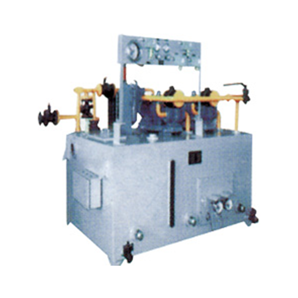
Figure 1-2-1 XHZ-6.3 ~ XHZ-125 thin oil lubrication device outline drawing

1. The flange connection size of the oil return port is in accordance with the provisions of JB / T81 "Convex panel flat welded steel pipe flange" (PN = 1MPa).
2. The thin oil lubrication devices listed above have no anchor bolt holes.

Figure 1-2-2 XHZ-6.3 ~ XHZ-125 schematic diagram

Figure 1-2-3 XHZ-160 ~ XHZ-500 outline drawing
VI.Dimensions


VII.Terminal wiring diagram


VIII.Electric control cabinet

IX.Dash board

Address: No.010 Xinglong Road, Huilong Industrial Park, Qidong City
Hotline:0513-83637668
Company Fax:0513-83637098
After sales service:0513-83635700
URL:www.qdhsrh.com
Website :en.qdhsrh.com
E-mail:qd3637668@163.com

Scan to learn more