

contact:Mr. Wang
Mobile phone:13862980878
hotline:0513-83637668
fax:0513-83637098
After sale:0513-83635700
mailbox:qd3637668@163.com
URL:www.qdhsrh.com
Website :en.qdhsrh.com
address:No.010 Xinglong Road, Huilong Industrial Park, Qidong City, Jiangsu Province
I.Conditions of Use
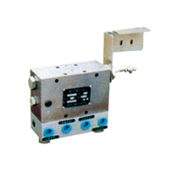
It is used in the electric ring type centralized lubrication system to alternately send the grease output from the pump to the two oil supply main pipes. It is directly reversed by the pressure control valve at the end of the oil supply main pipe. The set pressure of the reverse direction can be easily adjusted. The reversing valve has a simple structure and reliable operation.
II.Technical Parameters

Use a grease with a penetration of 265 to 385 (25 ° C, 150g) 1 / 10mm of grease.
III.Model label description

Use type code:
1. For DRB-L585Z-H lubrication pump
2. For DRB-L60Z-H, DRB-L60Y-H, DRB-L195Z-H, DRB-L195Y-H lubrication pump.
IV.Working principle
The figure on the right is a schematic diagram of the working principle of the hydraulic directional valve. In the picture, T1 ~ 4 ports are connected to the same outlet for the oil reservoir.
The grease output from the position 1 pump is sent from the oil inlet S to the oil supply main pipe L1 (line Ⅰ) through the passage formed by the main spool valve MP, and the pressure is applied to the main spool valve through the passage formed by the pilot spool valve Pp Left end. The fuel supply supervisor L2 is opened to the oil reservoir through the T1 port.
The end of the oil supply main pipe L1 is connected to the oil return port R1. When the pressure at the end exceeds the set pressure, the pilot spool valve is pushed to the right.
Position 2 The pilot spool valve P p moves to the right. The left cavity of the main spool valve M p is opened to the oil reservoir through the T3 port. The dry thin oil grease output by the pump is pressurized to the right end of the main spool valve and pushed it toward On the left, the contact on the indicator rod connected to the main spool valve hits the travel switch LS, and sends a signal to the electric control cabinet to stop the pump.
In position 3, the main spool valve M p moves to the left to complete the reversing action. The grease output by the pump again is sent to the main oil supply pipe L2 (line Ⅱ) through the passage formed by the main spool valve. The mouth is open to the oil reservoir.

V.Dimensions

VI.Instructions for use
The Y H F-L1 valve is matched with a pump with a flow rate of 585m l / m i n and is installed on the base plate. The Y H F-L2 valve is matched with a pump with a flow rate of 60 and 195m l / m i n and is installed on the pump body.
YHF-L1 valve adjustment screw turn the setting pressure right and turn left. The YHF-L2 valve is set to lower the right-hand pressure and increase the left-hand pressure.
When removing the YHL-L2 valve and the YHF-L1 valve cover from the pump body, first loosen the adjustment screw completely.
Address: No.010 Xinglong Road, Huilong Industrial Park, Qidong City
Hotline:0513-83637668
Company Fax:0513-83637098
After sales service:0513-83635700
URL:www.qdhsrh.com
Website :en.qdhsrh.com
E-mail:qd3637668@163.com

Scan to learn more